Bus Pirate and the MCP4725 DAC via I2C. Wow. What a mouthful. Following up on one of the most popular posts (SparkFun DAC Breakout Board Tutorial) in this guide we will take a look at controlling the MCP4725 DAC via the I2C protocol using a Bus Pirate from Dangerous Prototype. Before we get started let’s take a look at this video to see where we’re going:
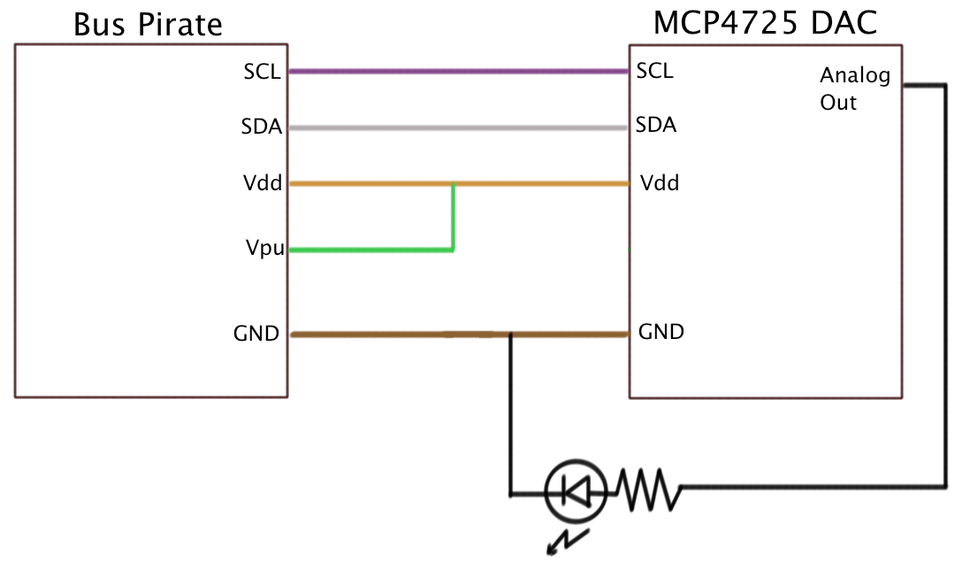
In short, we are going to drive an LED with varying voltage to control its brightness. We are going to drive the LED via the MCP4725 digital-to-analog converter. In turn, we will use the Bus Pirate to communicate to the MCP4725, and we will talk to the Bus Pirate via a serial connection and using the ZTerm terminal application. Obviously, this is a lot of work to turn an LED on and off. That’s only partly the point. When developing prototypes it can be a real pain to work with a lot of different microchips and the various communication protocols. This is the legwork to prepare to integrate a DAC into another project, where instead of using a Bus Pirate to drive the DAC chip, we will eventually use a Raspberry Pi. This will help us to make sure we know the I2C address of our MCP4725 chip and that it is working before we integrate into a larger and more complex project. Without further adieu, let’s get started. First a wiring diagram (color of the wires between the Bus Pirate and DAC are based on the color of the probe cables):

I am using 220-ohm resister and normal LED. There are many great tutorials on setting up the Bus Pirate for the I2C protocol, be sure to
start here. Some things that can trip you up. 1) Make sure you have the correct probe cables connected to the correct pins on the DAC. 2) Make sure the VPU probe for the pull up resistors is driven by the same power source driving the Vdd pin on the DAC. I am also assuming you know how to run a serial communication terminal software (TeraTerm or Putty or ZTerm). If not, again, there are many great tutorials already out there such as this one for
ZTerm. There are various settings you need toensure in the terminal software such as not setting the baud rate to 115200 or not turning off settings such asXon/Xoff. Once you get everything connected, you should see the following on the terminal screenHiZ>Meaning we are in high impedance mode which is a fairly safe mode, from a hardware perspective you will have less likelihood of frying a chip. Next we needto setup the Bus Pirate forI2C mode. Note that this is a based on a certain hardware revision and firmware version of theBusPirate. If you are reading this after a few years, the commands may have changed.HiZ>m
1. HiZ
2. 1-WIRE
3. UART
4. I2C
…
(1)> 4
Set Speed:
1. ~5KHz
2. ~50KHz
3. ~100KHz
4. ~400KHz(1)> 3
Ready
I2C>W
Power supplies ON
I2C>P
Pull-up resistors ON
I2C>(1)
Searching I2C address space. Found devices at:
0x00(0x00 W) 0xC0(0x60 W) 0xC1(0x60 R)
The above does the following:
1) Puts the Bus Pirate into I2C protocol mode
2) Sets the communication speed to 100KHz
3) Turns on the power supply to the DAC
4) Turns on the pull-up resistors on the I2C bus
5) Finds the address of theI2C devices connected to the bus pirate. In the case, 0xC0 for writing to the DAC and 0xC1 for reading from the DAC. Now to turn on the LED to full brightness enter the following:
I2C>[0xC0 0x0F 0xFF]
And in turn, the LED should go to full brightness and the serial terminal should display:
I2C START BIT
WRITE: 0xC0 ACK
WRITE: 0x0F ACK
WRITE: 0xFF ACK
I2C STOP BIT
To partially illuminate the LED enter:
I2C>[0xC0 0x08 0xFF]
Your mileage will vary based on the type of LED, resistor value, etc. You will have to tinker around a bit, but overall, this should get yourMCP4725 talking to the Bus Pirate. Next up, having the Raspberry doing the talking theMCP4725 DAC. For reference here is a waveform of I2C courtesy of the fine folks at intrepidcs.com